ISE&PPOOA is a requirements-driven, Model-Based Systems Engineering (MBSE) methodology where the main outcomes are the functional and physical architectures of the product, system, or service to be developed.
The ISE&PPOOA methodology is composed of two engineering processes; one named Integrated Systems Engineering (ISE) and other named Pipelines of Processes in Object-Oriented Architectures (PPOOA).
The integration between the systems engineering process and the PPOOA software architecting process is achieved by using domain modeling approach supported by UML class diagrams and CRC cards. If you do not want to use PPOOA framework for software you can use another software architecture framework instead, but we recommend you to use the domain model as the bridge between the system architecture developed using ISE and the software architecture.
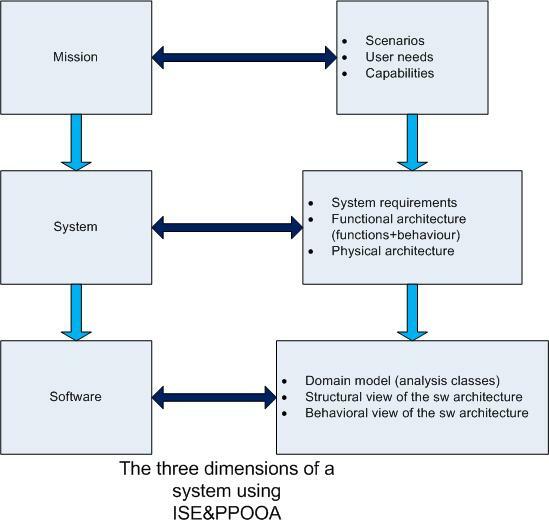
ISE&PPOOA views of the system can be envisioned as the assembly of the three dimensions, the last one used for software-intensive systems design
Each dimension has associated project deliverables, mainly SysML diagrams but complemented with textual and tabular representations, for example the N square chart
ISE&PPOOA is a tool independent methodology. You can use any tool that supports SysML notation

We will illustrate the application of the methodology to the Electronic Parking Brake System example. Here we are showing some of the diagrams developed for the mission and system dimensions.
The main mission dimension outcomes are the model of the system context or context diagram (SysML IBD); the identification of the main interactions between the system and external entities, including other systems, devices, people or environment (Use cases diagram); the description of the operational needs associated with these interactions (UC scenarios description and operational needs); and the definition of MOEs and capabilities.
It is important to realize that use cases represent interactions but some external interfaces, mainly the flows of matter and energy, cannot be represented as use cases, hence the importance of the context diagram.
Here we have some diagrams of the Electronic Parking Brake System mission dimension: Context diagram, use cases diagram and capabilities.


The main outcomes of the system dimension are the functional architecture, system requirements and physical architecture.
ISE&PPOOA defines a function as a transformation of inputs (material, energy, or data) into outputs (material, energy, or data). This definition of the function as a transformation allows the functional analysis and the modeling of the functional architecture for any system or process to be either physical or a software enabled system.
When building the functional architecture, we emulate the traditional approach of functional analysis, for example Ward and Mellor, but using SysML diagrams instead of DFDs. We follow three steps that can be performed iteratively:
From the functional architecture we obtain the complete system functional requirements. From the quality model (not represented here) we obtain the quality attributes requirements (QARs) or nonfunctional requirements.


ISE&PPOOA follows the principle “Form follows Function” coined by architect L. Sullivan, and therefore it proposes to define the Physical Modular Architecture from the Functional Architecture, maximizing cohesion and minimizing coupling between the system building elements.
So, this methodology defines the Physical Architecture in two major steps:
1. Define the Modular Architecture for the system by using functional allocation, other methodologies called it the logical architecture;
2. Refine that Modular Architecture by applying tradeoff analysis to synthesize the physical solution and heuristics to address the QARs or Nonfunctional Requirements, obtaining iteratively the final Physical Architecture.
In the first step, we focus on identifying physical building elements for our system in the form of modules. We will identify modules from the Functional Architecture, looking for groups of functions which are highly cohesive and coupled. The N-squared chart of the Functional Architecture plays a key role here.
Here, for the sake of brevity, we illustrate the approach with two diagrams. The first one is the breakdown of the system and the second is the IBD of the modular architecture of the system. Here the application of tradeoff and heuristics to obtain the refined architecture is not presented. See the resources page for examples of application of tradeoff and heuristics.

